Relief Valves
Relief Valves
What's the best way to avoid trouble? Seek the path of least resistance. While this may not be the best advice for all situations, it is helpful for us to know that fluids follow this cliché with predictable behavior. Applying this knowledge to your pump/system can prevent expensive downtime when component failure is caused by unavoidable or unexpected high pressure spikes. How do you compensate for high pressure spikes? A simple, but very effective, way is to install a relief valve.
The Relief Valve
The relief valve (also called a bypass valve) is a mechanism used to control or limit pressure by allowing the fluid to flow into an auxiliary passage, away from the main flow path. The relief valve is designed or set to activate at a predetermined pressure. When this pressure setting is exceeded, the relief valve becomes the “path of least resistance” as the valve is forced open and a portion of the fluid is diverted through the auxiliary route. The diverted fluid is usually returned back to either the reservoir or the pump inlet. Generally, the relief valve is used as a safety precaution bysetting a limit for the maximum operating pressure of the system or pump, ready to operate should the system exceed its pressure limits. The relief valve and bypass path can be internal (an integral part of the pump) or external (installed as a component in the fluid path).
Internal Bypass
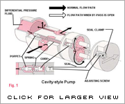
An internal bypass simply recirculates the fluid within the pump, returning the fluid from the outlet chamber to the inlet chamber. Cut-away views of a Series GJ and GB pump (see Fig. 1) show how discharge fluid fills the magnet cup. As the discharge pressure on the outlet side of the pump increases, so does the pressure within the magnet cup. When this pressure exceeds the force of the bypass spring holding down the poppet, it pushes the poppet off its "seat," allowing fluid to move through the auxiliary passage to the pump inlet. Bypass spring tension (and, consequently, bypass opening pressure) can be increased or decreased externally by adjusting the bypass screw (see Fig. 1).
This recirculation of fluid takes place in a small area (Fig. 1a) of the bypass. When the bypass remains open and the fluid is recirculated over a prolonged period, the energy of fluid movement and fluid friction will cause an increase in fluid temperature. Users should be aware that even when the fluid temperature in the system does not exceed recommended values, bypass conditions may create a sufficient temperature rise to cause significant swelling in PTFE-geared pumps. Fluid heating is a primary concern when the bypass is used to recirculate a large percentage of pumped fluid in small volume, closed-loop systems.
External Bypass
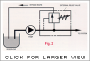
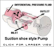
The external bypass is created by installing a relief valve in the system. Relief valves are available from several sources and typically operate on the same principle as explained previously: a poppet held in place with a spring is activated when the fluid pressure overcomes the force exerted by the spring. An external bypass is usually designed with the relief valve located close to the pump outlet and upstream of any other valves in the system. The diverted fluid should be directed back to the supply reservoir to avoid any possibility of fluid temperature problems as described previously. Figure 2 shows a possible bypass configuration.
Relief Valve Characteristics
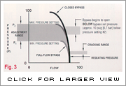
Closed bypass This is when the relief valve is closed. In our pumps, this occurs when the adjusting screw is turned all the way in (clockwise), compressing the bypass spring all the way, and the pump experiences full-flow and pressure-producing capabilities.
Cracking pressure This is the pressure at which fluid begins to flow through the relief valve.
Full-flow bypass pressure This is the fluid pressure when maximum flow is passing through the relief valve and bypass path. In our pumps, 100% of the bypass output is recirculated.
Reseating pressure This is the fluid pressure when the relief valve is completely closed. Reseating pressure is lower than the cracking pressure.
Note, as shown in Fig. 3, that our bypass does not go immediately from activation to full-flow. Full-flow bypass occurs gradually over an approximate 0.7 bar (10 psig) range.
Valve Selection and Setting
Relief valves should be “set” to open at a pressure above the operating pressure. This provides system safety. Care should be taken when determining the maximum system pressure. Use the component with the lowest pressure rating as a guide for establishing your limit. Don't forget, this component could be the tubing!
In fluid handling applications, many markets have systems where high flow/low pressure is needed in one phase, followed by low flow/high pressure needs in the next phase. As always, the system and pump designer must conserve power, prevent temperature increases, and provide reliable solutions immediately (or sooner). The bypass valve offers a means of solving system problems and providing safety in a practical manner, without breaking tight budgets. So consider the path of least resistance on the way to your next solution. You may find relief!
Find a Distributor
Get a Quote
Find a Product
Headquarters
1402 NE 136th Avenue
Vancouver, WA 98684-0818 USA